Reduce Each of the Networks Shown in Figure P2.1
Then eliminating two loops results in Figure 3-43b. Resistances in Series and Parallel P21.

Solved Section 2 1 Resistances In Series And Parallel Chegg Com
First move the branch point of the path involving HI outside the loop involving H as shown in Figure 3-43a.

. 3Q 3Q 30Q 12Q 24Q 7Q 4Q a lOQ 6Q 24Q 1s n 60Q 9Q sn 6Q b Figure P21 P22. Figure 2 AnsRab99 3. Obtain the bus admittance matrix for the admittance network shown aside by the rule of inspection.
Finally divide the source volt-age by the current to determine the equiv-alent resistance looking into the terminals. Draw the resulting reduced system. Find the equivalent resistance between terminals a and b in Figure.
Figure 1 AnsReq23 2. Dv 1 dt i 2 3 di 3 dt v L 2 Therefore the state vector is x v 1 i 3. 10 Ω 10 Ω 50 Ω s 60 Ω 20 Ω Λ 20 Ω 10 Ω a 10 Ω 10 Ω 50 Ω s 20 Ω 20 Ω 10 Ω M 10 Ω 20 Ω b.
As always the exact approach depends on what we want to know about the circuit but resistor reduction is a tool that we will use over and over. In this question Find the transfer function as per given input and output voltage. Electrical Engineering questions and answers.
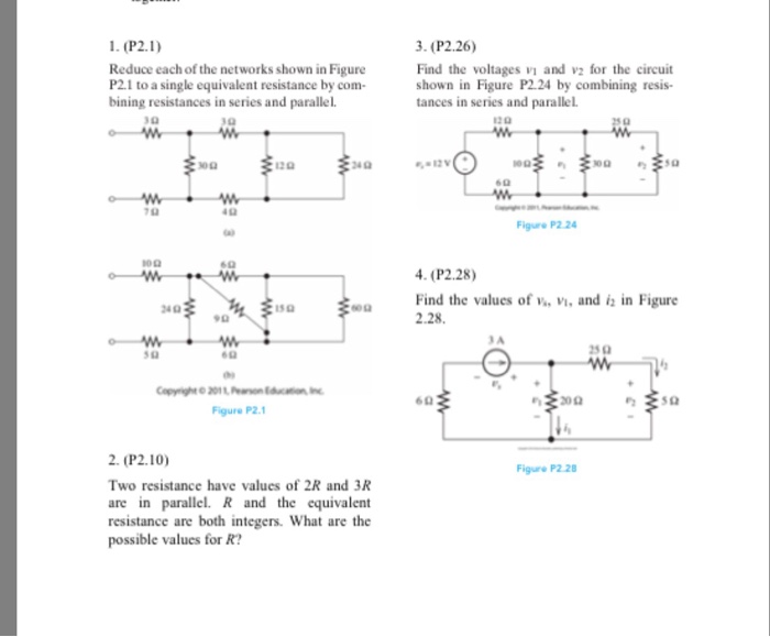
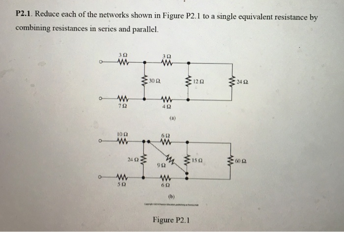
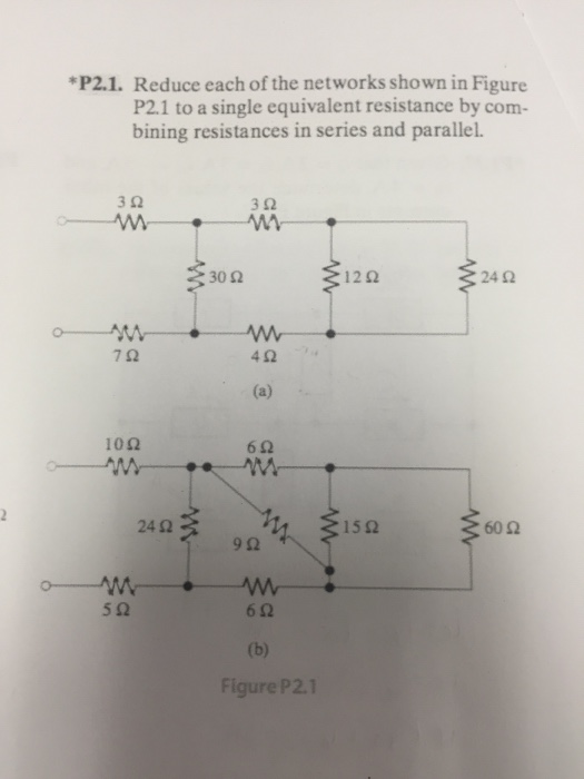
Reduce each of the networks shown in Figure P2l to a single equivalent resistance by com- bining resistances in series and parallel. Reduce each of the networks shown in Figure P21 to a single equivalent resistance by com- bining resistances in series and parallel. Reduce each of the networks shown in Figure P21 to a single equiva.
Connect a 1-V voltage source across the terminals of the network shown in Figure P21aThensolve the network by the mesh-current technique to find the current through the source. 3Ω 3 0 30 Ω 12 0 24 N 7Ω 4 0 a 10 Ω 24 N 15 N 60 Ω 6Ω b Figure P21. Define the mesh currents flowing around each of.
Resistances in Series and Parallel P21. The equivalent resistance for the network is 8 Ω. Reduce each of the networks shown in Figure P21 to a single equivalent resistance by combining resistances in series and parallel.
Also determine YBUS for the reduced network after eliminating the eligible unwanted node. R 3 R 4 R 5 R 2 R 1 V S i S 1 kΩ 22 kΩ 330 Ω 470. See Appendix E for more information about accessing the Student Solutions.
Reduce each of the networks shown in Figure P21 to a single equivalent resistance by combining resistances in series and parallel. Find the equivalent resistance between terminals a and b in Figure 2. Av aO5S Figure PI 71 PI42.
A 4- resistance is in series with the parallel combination of a 20-. Denotes that answers are contained in the Student Solutions files. The equivalent resis-tance for the network.
Reduce each of the networks shown in Figure P21 to a single equivalent resistance by combining resistances in series and parallel. Answer a R_e q20 Omega. Determine the value of R x.
Now obtain v L and i 2 in terms of the state. Step-by-Step Solution Request Professional Solution. Reduce each of the networks shown in Figure P1 to a single equivalent resistance by com-bining resistances in series and parallel.
Devise a network of 1-kS2 resistors so the equivalent. We start with resistors. State Space Representation of Electrical Networks aRepresent the electrical network shown below in state space where i Rt is the output.
Reduce each of the networks shown in Figure 1 to a single equivalent resistance by combining resistances in series and parallel. Finally divide the source voltage by the current to determine the equivalent resistance looking into the terminals. 18 Q Figure P24 Suppose that we need a resistance of 15 kS2 and you have a box of 1-kS2 resistors.
Write the di erential equations for each energy storage element. Denotes that answers are contained in the Student Solutions files. 3n 311 h----- 3011 7n Ion sn 4n a 6n 6n b 12.
Then solve the network by the meshcurrent technique to find the current through the source. Find the transfer function Gs Vs Vis for each network shown in Figure P25. Simplify the block diagram shown in Figure 3-42.
Reduce each of the networks shown in Figure P21 to a single equivalent resistance by combining resistances in series and parallel. Combining two blocks into one gives Figure 3-33c. Simplify the block diagram shown in Figure 3-13.
Reduce each of the networks shown in Figure P21 to a single equivalent resistance by combining resistances in series and parallel. Reduce each of the networks shown in Figure P21 to a single equivalent resistance by com- bining resistances in series and parallel. 10 Q 30 Q a b Figure P21 12 Q 15 Q 24 Q 60 Q PI71.
Combining the resistances shown in Figure P213b we have 5Req 1 8 16 Req 8 5 Req 1 5 1 Req. A 4-Q resistance is in series with the paral-lel combination of a 20-Q resistance and an unknown resistance Rx. Reduce each of the networks shown in Figure P21 to a single equivalent resistance by com- bining resistances in series and parallel.
Reduce each of the networks shown in Figure P21 to a single equivalent resistance by combining resistances in series and parallel. Reduce each of the networks shown in Figure P21 to a single equivalent resistance by combining resistances in series and parallel. Find the values of i1 and i2 in Figure 3.
In many situations we can reduce complex resistor networks down to a few or even a single equivalent resistance. Find the equivalent resistance looking into terminals a and b in Fi. A 4-Ω resistance is in series with the parallel combination of a 20-Ω resistance and an unknown resistance R x.
Obtain YBUS and ZBUS matrices for the impedance network shown aside by the rule of inspection. A 3 Ω 7 Ω 30 Ω 24 Ω 3 Ω 4 Ω 12 Ω b 10 Ω 5 Ω 24 Ω 60 Ω 6 Ω 6 Ω 15 Ω 9 Ω FigureP21 P22. What type of controlled source is shown in the circuit of Figure Pl71.
Additional Problems in Homework 1 1. Connect a 1-mathrmV voltage source across the terminals of the network shown in Figure P21a.

Solved Reduce Each Of The Networks Shown In Figure P2 1 To A Chegg Com

Solved P2 1 Reduce Each Of The Networks Shown In Figure Chegg Com

Solved Reduce Each Of The Networks Shown In Figure P2 1 To A Chegg Com
Comments
Post a Comment